SPACE FRAME SYSTEM
05
SPACE ROOF SYSTEM
Space Frame System Structures are three-dimensional hyperstatic structural systems whose main elements are rod elements and point node elements. Despite being understood and practiced as large-scale roof systems, space cage structures are architectural and constructive post-modern building systems that can provide very different functions.
BENEFITS
Space Frame Structures are noted with its general characteristics briefly outlined below with its advantages and wide application areas offered to the building sector.
»SPACE CAGE STRUCTURES are systems that can provide full distributions of hyperstatic and three dimensional loads
To understand the hyperstatic structure of Space Frame systems, a short comparison with alternative plane frame systems will suffice.
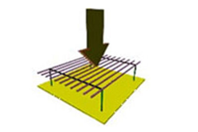
In plane cage frame systems (in scissor roof systems) the carrier construction is formed in the same plane. The scissors manufactured in this way are distributed in two dimensions on the same plane in the roofs (Fig. 2.a). Planar roof scissor constructions made in a similar manner are arranged parallel to each other on the roof and are connected to each other in a perpendicular direction. For these reasons, load distributions are carried out in perpendicular planes. Because of this, the steel elements are exposed to large loads as they can be transferred to a restricted geometry, which results in structural designs made with very heavy sections, especially in large openings.
Furthermore, the reactions occurring between the plane shear roof and the carrier structure can not be distributed in a very stable manner, which makes the carrier infrastructure more costly.
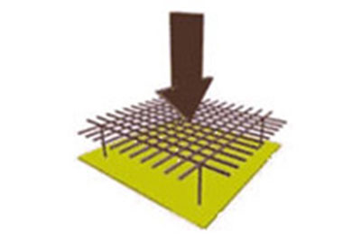
However, space cage systems provide best load distribution by connecting the lower horizontal and upper horizontal rods, which form itself from the first support, to the diagonal rods in 3D. (Fig. 2.b) The sudden and large loads that can occur in this vault are divided into small pieces and transferred to the knot elements by the rod elements of circular diameter with minimum diameter. In addition, since moments are zero in point node elements, the node elements do not transmit doume effect and moment. All elements are assumed to be subjected only to axial pressure and tensile forces.
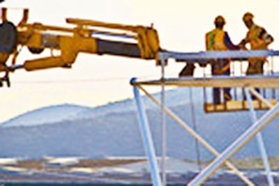
»SPACE CAGE STRUCTURES is a type of building that can be manufactured and assembled very fast with its prefabricated feature.
Due to the fact that space cage structures are made entirely in the factory and outside the construction site, the manufacturing and installation time is very short, which gives the building sector and investors an important advantage. Depending on the location and environment conditions, the installation is partially and completely carried out on the ground and then it is mounted on the supports by lifting the roof with mobile crane or special lifting devices or it is being installed by using special movable scaffolds and platforms at the roof level. It is evident that the geometry of the construction period depends on the installation conditions and the fastest installation for the alternatives
»SPACE CAGE BUILDINGS, ONLY ALTERNATIVE IN GREAT VIEWS.
In factories, workshops, warehouses, supermarkets, etc., it is necessary that the roof system should be able to cross the wide openings, as it is often the case that the transport of the conveying columns, the storage of the goods and the general circulation are not obstructed. This requirement can not be ensured sufficiently in structures made with steel plane or reinforced concrete scissor roof systems. The Space Cage Roof System is a convenient system for passing very large openings. In most of the free openings of 25 m, the space roof system is preferred as the most suitable system in terms of economic costs and ease of installation and speed. Continuous use of the space also results in significant financial savings during operation.
»SPACE CAGE STRUCTURES, SAME STANDARD BUILDING AESTHETIC PARTICULARS.
Space frame systems offer a variety of building alternatives to designers according to the shape and geometry of the structure. A wide variety of post-modern horizontal and vertical steel structures can be constructed using square, triangular, hexagonal space cage modules. This complexity can be solved very quickly in this way, which brings great comfort to the designer. The fact that the system can be painted in the desired color also makes it easy for buildings to have an unusual appearance.
»SPACE CAGE STRUCTURES bring great convenience as a feature of the system when using all kinds of service load.
In addition to providing easy installation of the extra holes to be opened on the point connectors of the space cage structures, it also acts as a natural fixing point for every service load. Elements such as lighting fixtures, suspended ceilings, ventilation ducts, electrical installations can easily be mounted on the roof by means of screwed fasteners without any damage to the roof.
»SPACE CAGE SYSTEMS, LIGHT SYSTEMS.
Another feature of the space cage constructions is that it is much lighter than the concrete and scissors roof systems. Because of the small load, the carrier column sections and basic production are shrinking to provide a great economy in the investment phase.
»SPACE CAGE STRUCTURES are a choice of structures that can be used in many different ways and for different purposes.
Space frame structures are widely used for a number of purposes in just a few of the places
mentioned below.
● Shopping Centers, Supermarkets, Hypermarkets and Market Places
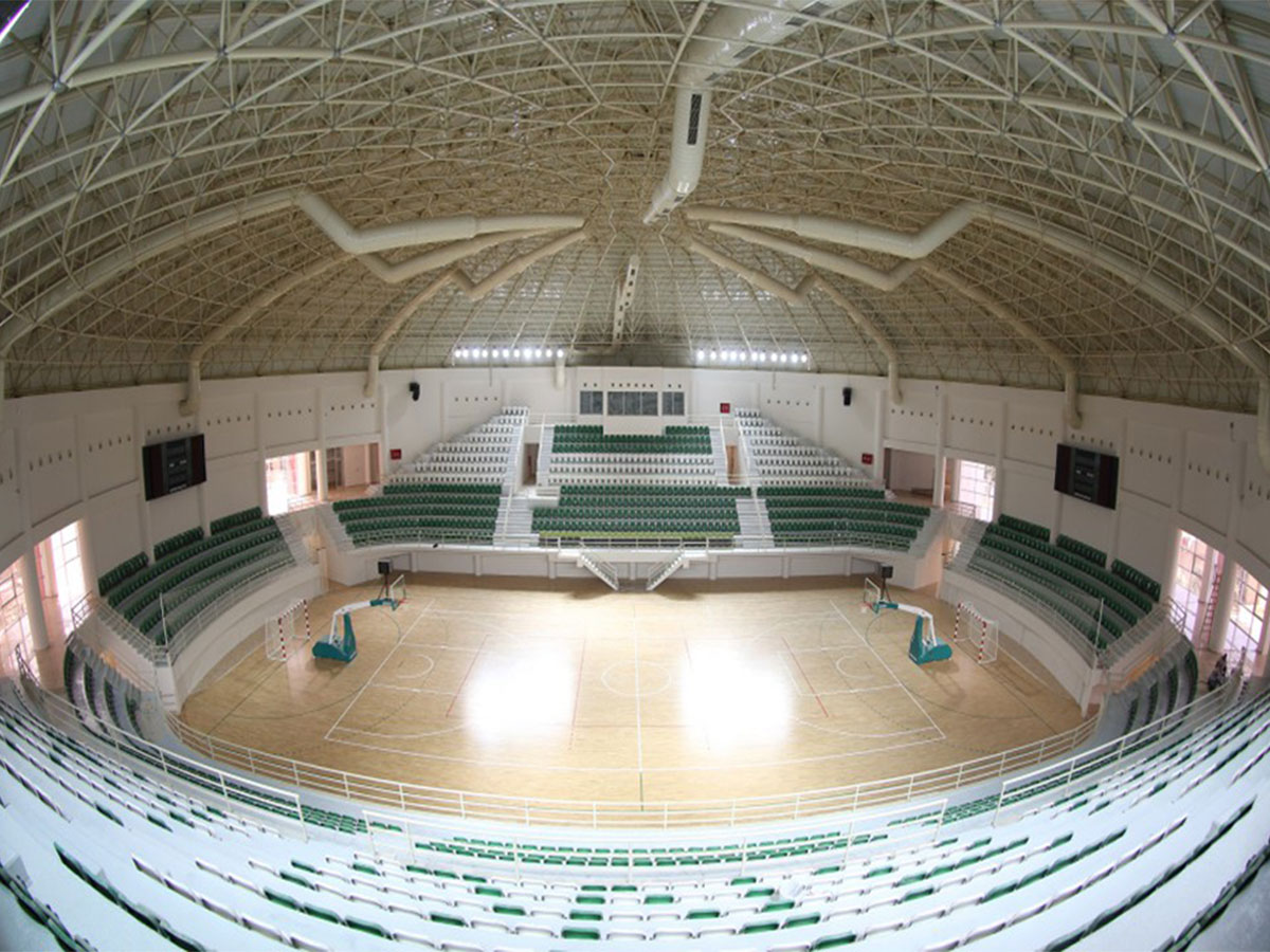
● Sports Hall, Indoor Swimming Pools, Tennis Courts, Equestrian Maneuvers and Multi-purpose Sports Facilities
● Stadiums and Shops, Aircraft Hangars
● Trolleys, Terminal Buildings and Parking Garages
● Gas Station Stations
● Stadiums , Indoor Tirübün Çaları
● Cinema, Theater, Conference Halls, Performing Arts Centers, Weddings or Multipurpose Halls
● Overpass and Tube Passages
TECHNICAL SPECIFICATIONS
It is the modular system concept that constitutes the basic element that provides the prefabricated
structure feature that Space Cage Systems possess. The type of module that makes up the structure
can be square, rectangular, triangular, hexagonal depending on the choice to be made during the
design phase.
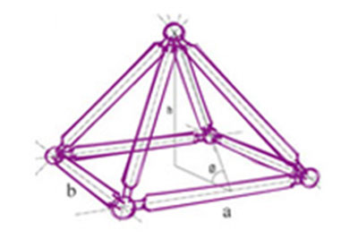
A module is defined by the following parameters; a = module size in x-direction
h = module depth,
qx, qy = module angles
In the selection of the module, economics, manufacturing and assembly facilities, structural analysis
requirements to be made under the loads to which the system is exposed, geometric conditions (axle
spacing, etc.) and aesthetic elements should be considered.
Some key criteria for designing in Space Frame Structures are summarized below;
1-) The type of square module is the most frequently used and used because of the easiness of manufacturing and installation and the best load distribution. In this mode a = b; Equality and module depth are determined.
Furthermore, in this type of module, manufacturing and installation are provided with great convenience and therefore economy, it is known as standard type module. In the standard module type, the horizontal rod elements and the diagonal rod elements are in equal axial lengths. The necessary condition for this is; diagonal rod element axle size;
d = a => q = 540, 44 , h = a x sin(45)
2-) Also, due to geometric and static constraints, the module angle q, unless it is very compulsory; 600> qx, y> 300. Otherwise, the 3-D load distribution characteristic that gives the system the hyperstatic structure characteristic will be greatly reduced, and the system will show a load distribution characteristic close to the 2-dimensional system. Moreover, it is almost impossible for the spheres forming the nodes to approach the bar elements at these angles without striking each other, and therefore it is necessary to enlarge the sphere diameters to the extreme and disproportionate to the system.
3-) Another important consequence of this is the proportional relationship between module dimensions and depth. Accordingly, a> h> a / 2 should be. Another change is that the system depth should be selected between the half of the module size and itself.
4-) The proportional relation between the depth of the roof system and the critical opening is described by recent studies and it is accepted as a preliminary design criterion especially for static projects before the project. According to this ;
L = critical, free opening, d = module depth
In a square or rectangular module system, each module consists of 5 spherical knot elements and 8 rod elements. However, considering the common elements in repeating modules, 2 spherical elements and 8 rod elements in each module will be used in the system. For this reason, the selection of the module type and especially the dimensions (a, b, h) directly affects the system weight and hence the cost.
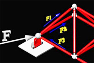
In the Space Frame system used as a roof construction, the rod elements can not receive a direct moment. They only receive axial pressure and pulling force.
Loads are transferred to the steel spheres, which are the connection element of the system first through lovers, and then transferred to the rod elements and distributed in 3 dimensions in the roof system.
ROD ELEMENT PIPES
The main elements of the system are the S185JR, J0, J2 QUALITY, S235JR, S235J0, and S305JR, which have low carbon ratios according to TS 301/3 and DIN 17100 norms, provided in steel adapters welded with a conical form with hot forging technique on both ends, S235J2 QUALITY or S275JR, J0, J2 QUALITY quality materials are circular cross-section and welded pipes. Steel traction pipes can also be used in special cases. We use materials with S185, S235, S275, S355 quality and JR, J0, J2 impact toughness according to the climate and weather conditions or environment conditions of the products where the application will be done.
Nominal diameter |
inc |
3/8" |
1/2" |
3/4" |
1" |
1 1/4" |
1 1/2" |
2" |
2 1/2" |
3" |
4" |
5" |
6" |
|
mm |
10 |
15 |
20 |
25 |
32 |
40 |
50 |
65 |
80 |
100 |
125 |
150 |
Outer diameter |
mm |
17,2 |
21,3 |
26,9 |
33,7 |
42,4 |
48,3 |
60,3 |
76,1 |
88,9 |
114,3 |
139,7 |
165,1 |
Pipe thickness |
mm |
2,35 |
2,65 |
2,65 |
3,25 |
3,25 |
3,25 |
3,65 |
3,65 |
4,05 |
4,5 |
4,85 |
4,85 |
CONICIAL
Conics, C1020 - C1030 and S235 - S355 quality materials are used. weldability is manufactured by machining or hot-stamping according to their diameter from high steel materials and they are fixed by using gas welding method on both ends of the rod elements. Welding is done semi-automatically on special benches without touching hands. In this way, the mistakes that can arise from the workers have been removed.
BOLTS
Bolts are manufactured specially for Space System and bolt tests are made and evaluated according to ISO 898-1. The bolts used in the system are elements that act against the draw in the bar elements. In accordance with the results of the static analysis, the appropriate quality and quality are selected. It is usually made and tested according to the mechanical properties described in ISO 898-1. 8.8 (6400 Kg / cm2 elongation, 8000 Kg / cm2 elongation) and 10.9 (9000 Kg / cm2 elongation and 10400 Kg / cm2 elongation).
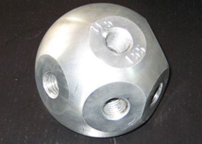
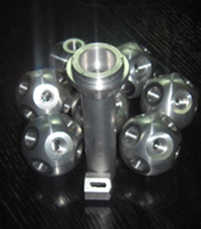
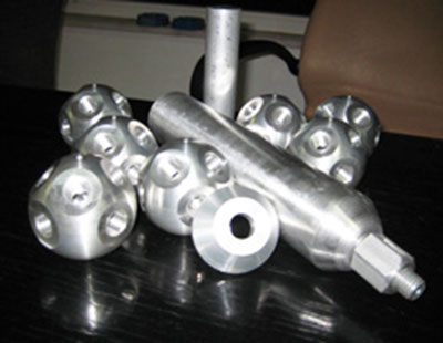
NUTS
In the system, it works both against axial pressure loads with the rod element and it is the parts that enable the ball to be tightened by using the key during assembly. St-37 is produced in quality steel by machining method and in appropriate sizes, the grooves are opened in eccentric presses using special molds. The diameter and wall thickness of the nuts also vary depending on the pressure force to be exposed and are manufactured specially. Steel spheres, which are one of the connecting elements of the system, are produced from steel material of C1040 quality according to DIN 17200 norm, spherical form with hot forging technique and full body. In Space System Space Frame Constructions 60,75,90,110,132,154,160,190,132,154,160,190,200,240 mm spheres are used according to the static and geometric requirements of our projects. Depending on the number of the elements to be connected to the spheres, the holes corresponding to the geometry of the work are drilled in the special machines and metric teeth are opened according to DIN13 norm. A maximum of 18 holes can be drilled on a sphere. The holes can be used for the application of service loads and for the mounting of lovers, in addition to the assembly of rod elements.
DESIGN
The UZAY SISTEM prepares the design of the space cage constructions to be carried out under consideration, the infrastructure to carry the space cage system and all the architectural and technical conditions of the roof superstructure. For this purpose, it provides the highest level of cooperation with other project groups at the design stage as well as at every stage of the project. In this sense,
»Modulation selection is made according to the desired architectural aesthetic and functions.
»Architectural alternative settlement studies are done
»Carrier infrastructure qualities are examined and selection of the supporting systems and types according to all horizontal and vertical loads transferred from the space cage structure is carried out.
»If requested, consulting services including computer-aided photography and realistic imaging studies will guide the design before implementation.
»In addition, after the control of static and dynamic behavior of the space cage structure and the selection of the modulation, the details of the structure and superstructure of the structure are studied.
»At this stage, the supports are dimensioned, point details are created in accordance with the required requirements of the loft system and the rainwater drainage systems which will constitute the infrastructure for the coating.
»Prior to finalizing the selection of the system, preliminary analyzes shall be made on request and all horizontal and vertical loads to be transferred to the carrier infrastructure shall be reported to the owner of the displacement values in view of the carrier infrastructure and healthy working conditions.
»For this purpose, all the necessary work is done with dedication.
STRUCTURAL ANALYSIS
In order for the structural analysis studies to be carried out properly, all data related to the system should be identified
Accordingly, the geometry of the structure, support points and types, all horizontal and vertical loads to be affected by the structure, the temperature difference to affect the structure, are modeled in the system computer environment according to the definition of special loads.
The loads to be affected by the system are as follows.
Vertical Loads:
Zati Load
Dead Loads:
Profit: Loads specified in TSE 498 apply to the minimum. However, at least 50% load increase is predicted due to icing, rain effect and heavy snowfall effect.
Lovers: The actual values of the lover system are determined by the SPACE SYSTEM. Coating: Actual values are given by the customer. Service Loads: Catway, Installation, Electricity, Suspended Ceiling, etc ..
Mobile Loads: Human loads, mobile service loads
Horizontal Loads :
Wind Load: It shall be effected in accordance with TSE 498 at least in each direction and in accordance with special conditions
Earthquake: Equivalent earthquake load calculated according to the latest earthquake regulations and earthquake areas specified in TS498 is carried to the system as uniformly distributed horizontal load.
The completed model is placed on the architectural project and the geometric control of the model is made. Structural analysis of the system is done by means of special software which operates by means of the finite element method of UZAY SISTEM. All calculations are made in accordance with TS and International norms
MANUFACTURING
»One of the most important stages of space cage production is welding of rod elements. Semiautomatic and computer-aided machines for this process, UZAY SISTEM itself by designing, production has done.
»The data for the manufacture of the elements to be welded in the looms are sent from the central computer and the axle measurements are also adjusted numerically. In this way, the transfer of the workbench is automatically adjusted, and all possible faults are removed altogether.
»The globes are all hand-touched, computer-aided and numerically controlled. Structured analysis programs are transmitted to the transaction center via the computer, which is formatted in the resulting files. For this reason, spheres, which are the most sensitive production points of space cage structures, are processed completely without errors.
»Intermediate products to be used in space cage manufacturing are manufactured on the own machines of Space System by machining method.
»Supports, in love professors, lovers in love, etc. accessories are designed by technical staff of SPACE SYSTEM and manufactured in accordance with the project.
»» »After the manufacturing of all elements, painting and coating processes are carried out at the own production facilities of UZAY SİSTEM. As standard, the rod elements are covered with polyester based powder paint in electrostatic powder coating furnace after numerical control after cleaning in accordance with the technical specifications of the loose stitches and profiles.
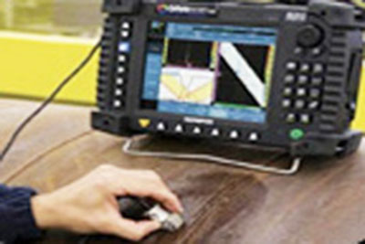
QUALITY CONTROL
UZAY SISTEM has designed and built an ISO quality management system suitable for the production of space cage systems with the aim of creating an effective control system at every stage of the work. In addition, TSE has a manufacturing qualification certificate and TSEK quality certificate.
Starting from the project works, all the processes from procurement, material supply, storage, manufacturing, shipping, installation and post-installation inspection are carried out in accordance with the instructions and procedures defined in the quality control system. The aim is to supervise and develop the whole system and the quality control officer is constantly serving.
According to the said quality control system;
All orders for the supply of necessary materials are made by receiving offers from approved suppliers of SPACE SYSTEM. The ordered materials are accepted by carrying out the necessary tests in accordance with the acceptance procedures defined in the procurement procedures specified in the quality management system.
At the manufacturing stage, all manufacturing measurements are inspected by continuous quality control personnel and every transaction is recorded.
In addition to physical inspection and measurement controls, mechanical impact and non-impact tests are periodically performed
Electrostatic powder coating and metal coating processes are controlled by measuring the coating thicknesses after coating with numerical measuring instruments. For each baking process, mechanical adhesion tests are carried out and recorded.
ASSEMBLY
All installation works in the SPACE SYSTEM are made according to the preliminary plan according to the results of the inspection done at the installation site during the preliminary studies of the project.
Mounting area; The carrier infrastructure system is examined in light of how to design and transport the cargoes to be transferred from the roof system to be designed, and digital photographs of the relevant point details are taken.
LAST CHECK
Following the completion of the installation, the physical inspection, measurement and postinstallation inspections are carried out by the technical staff of SPACE SYSTEM to ensure that the work is completed as designed in the project.
»Critical max displacements are measured in the system. The standard report is prepared after montage by checking all the subjects such as whether the brackets are made according to the project of on-site welds, whether all the screws are tightened tightly, etc.
»Performance grades are given to the production group and assemblers.
02